

Wind Turbine Technologies |
|
|
Over the years, a dominant design has emerged, which consists of 3 blades, mostly up-wind rotor, pitch-control for braking and an integrated gear box. However, in this context, "dominant" does not necessarily mean "best". The best turbine technology for a given project depends on the site's precise wind profile and other requirements. This is why many variations exist. |
 Wind turbine technologies have evolved over centuries from traditional wind mills to the slick turbines we know today. Developing a wind turbine requires a number of design decisions, starting from the axis orientation, and number of blades to choice of material.
The most widely used application is the wind anemometer with its moving cups. Small-scale roof-top turbines are also often with a vertical axis to avoid gear box.
|
Lift
|
Drag
|
|
|
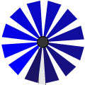
Darrieus

tip speed ratio: 4
|
Savonius

tip speed ratio: <1
|
Wind Anemometer
|
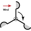
- Omni-direction - wind may come from any direction
- Easy to mount at ground level, no tower needed
- Low rotation speed - no gearbox needed - less noise
- Generally near the ground with low wind speeds
- Self-starting problems
- Drag devices capture only ~15% of energy, Darrieus ~40%.
- No large-scale commercial application
Horizontal axis is the most common design for turbines, and is also the design of the traditional wind mills. For electricity generation, mostly 3 blades or less.
|
|
||
|
1 Blade

Tip speed ratio:12
|
3 Blades

Tip speed ratio: 6
|
Water Pumps
Tip speed ratio: 1
|
- Tip speed ratio is the ratio of the tangential velocity of the blade (at the tip) to the undisturbed wind speed. Fewer blades means higher tip speed. The optimum tip speed ratio that maximises the lift-to-drag force ratio is around 8. With more than 4 blades, less efficiency because each blade operates in the wake of others.
- Efficiencies up to 50%
- Lower cut-in wind speeds than vertical turbines

|
|
|
|
A control mechanism is an overspeed control that allows the rotors to be slowed down or stopped. Its purpose is to
- optimize aerodynamic efficiency
- keep the generator with its speed and torque limits and rotor and tower within strength limits
- enable maintenance
- educe noise
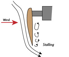
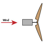
- Passive: Blades are at a fixed pitch that starts to stall when the wind speed is too high.
- Active: motor turns the blades towards stall when wind speeds are too high.
- Hybrid: Pitch can be adjusted manually to reflect site's particular wind regime.
- Disadvantage: Stalled blades cause large vibration and therefore noise.

Always active control: Blades rotate out of the wind when wind speeds are too high.
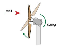
Standard modern turbines all furl in high wind.
- Requires active pitch control: Pitch angle of the blades needs to be minimised first, otherwise the torque on the rotor would be to big for furling.
- Active: Vertical furling (as diagram) with hyrdraulic, spring-loaded or electric motor driven.
- Passive: Horizontal furling with yaw
Indirect: The rotor drives a gearbox, which drives the asynchronous generator at around 1000rpm.
- Laminated wood
- Aluminium
- Lightweight glass-enforced plastic - this is most common among large blades - 50 to 100m long.
Yaw mechanism moves the nacelle of a horizontal turbine around its tower into the wind when the wind direction changes.
- Passive: with a fin attached to the nacelle on the opposite side of the rotor.
- Active: with a motor
Steel tube
- Bending and welding in factory
- Long experience
- Steel is expensive.
- Transporting on the ground subject to size limits 4-5m.
- Example: REpower
Lattice tower:
- Less steel than steel tube.
- Good for high towers
- Constructed on-site
- Requires lots of inspection and on-site labour.
- Example: SeeBa, Suzlon
Concrete tower:
- Less use of expensive steel
- Quality problems with on-site concrete. due to changing weather conditions. Alternative: ship segments from manufactury subject to transport limits.
- Example: Enercon